

4 min read
When a post acceleration HV stack starts to fail, the fault rarely stays in one place. This is the story of one stack through our repair centre: an Applied Materials POST ACCEL HV STACK 160kV (OEM number 0090-90389) that came back to us with its voltage breaking down in service.
It is a good example of how a stack fails, why one worn component rarely fails alone, and how we prove a repaired stack is fit to go back on the tool.
New to HV stacks? Our guide to how high voltage stacks work covers the basics.
The fault: voltage breaking down in service
The customer reported that the stack could no longer hold its voltage. On an ion implanter, the post acceleration stage gives ions their final energy, so an unstable stack means unstable beam energy and lost tool time.
Breakdown like this usually points to insulation that can no longer stand off the voltage across it. Our job was to find where, and why.
What we found: all eight multiplier rings degraded
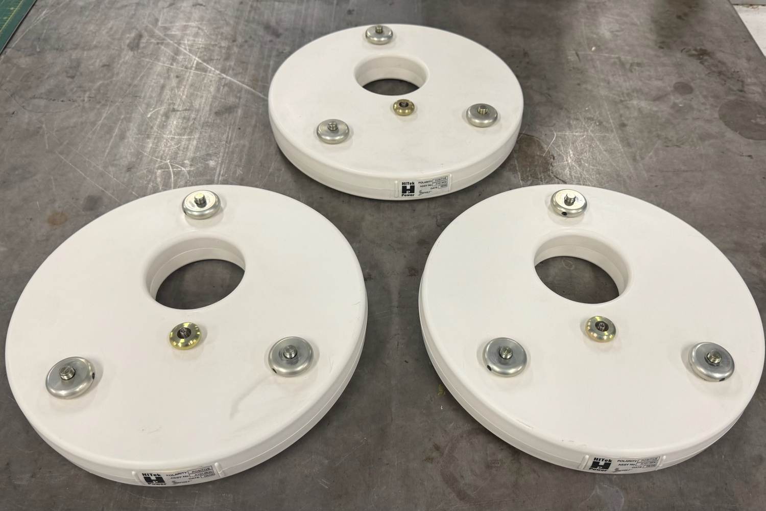
The stack is built from eight high voltage multiplier rings, stacked one on top of the next. On inspection, every one of them showed clear signs of degradation.
The giveaway was separation within the plastic body of each ring: a visible line running around its circumference where the moulding has started to come apart. Once that happens, the ring can no longer insulate properly, and the voltage looks for the easiest path to ground.
That is exactly the voltage breakdown the customer was seeing.
The knock-on damage: a burnt-out voltage divider
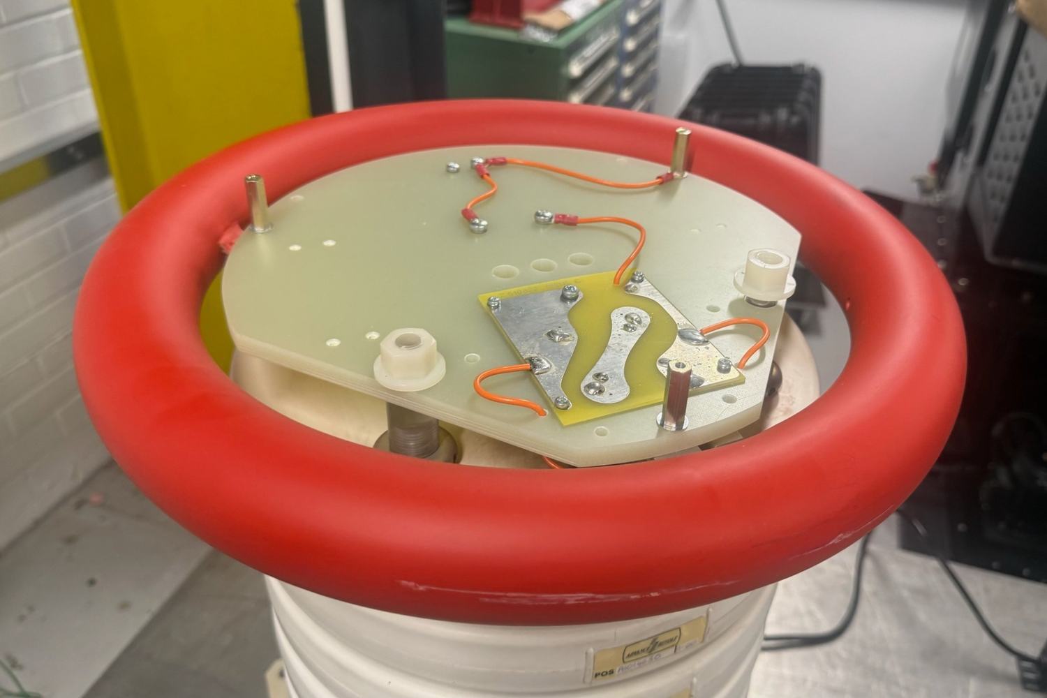
When we dismantled the stack, the rings turned out not to be the only casualty. Their condition had caused arcing onto the central voltage divider, which runs up through the middle of the stack.
The divider was damaged beyond repair and had to be replaced. This is the real cost of running a failing stack: a fault that starts in the rings spreads to the parts around it, and the repair grows with every hour it stays in service.
Why we replace the rings as a complete set
It can be tempting to swap out only the worst rings. In our experience that is a false economy. Rings in this condition keep deteriorating in service and start to arc between adjacent stages, so a stack with one new ring and seven tired ones is still a stack waiting to fail.
We replaced all eight with the same part number from a later year of manufacture, and confirmed each one was free of the degradation found on the originals. The result is a stack where every stage starts its working life from the same point.
How we test a 160 kV stack
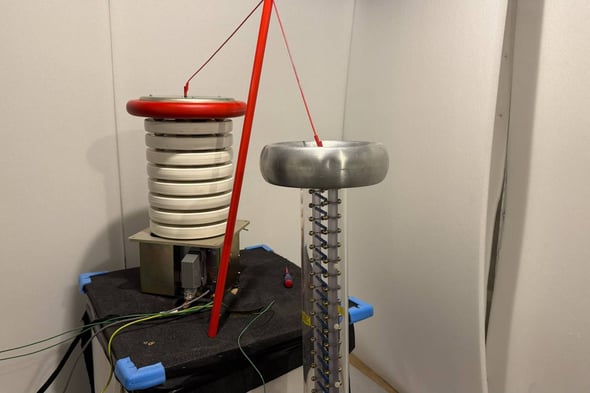
A repaired stack is only as good as the test that proves it. Every stack goes through a full functional test at voltage in our EMC room before it leaves us.
- Drive: a 6 kW Hivolt converter powers the stack, just as it would be powered on the tool.
- Demand: a Fluke 715 calibration source commands the converter from 1 V to 10 V in 1 V steps, with 10 V as maximum demand.
- Measurement: the stack's output is read through a Spellman 200 kV voltage divider, scaled at 1 V per 100 kV, while a Fluke 3000FC monitors the converter and stack.
At each step the stack is allowed to settle before we record the output and the converter's readback signal. Throughout the sweep we watch for any instability, breakdown or arcing of the kind the customer reported.
The result: 10 out of 10 test points passed
The repaired stack passed at every one of the ten setpoints. Output rose smoothly with demand, reaching 165.4 kV at full demand, comfortably meeting its 160 kV design output. Both the high voltage output and the converter readback tracked demand in a straight line, with a coefficient of determination of 0.998.
Most importantly, there was no instability, voltage breakdown or arcing at any point in the test. No defects were outstanding, and the stack was signed off as a pass.
What to take away
- Look for the warning signs. Separation in the plastic body of multiplier rings is a reliable sign they are failing.
- Act early. Left in service, failing rings arc onto neighbouring parts, and a ring replacement becomes a divider replacement too.
- Replace as a set. Swapping single rings leaves the rest of the stack to fail next.
- Insist on proof. A full test at voltage, with every setpoint recorded, is what tells you the stack is ready for the tool.
Get your stack back on the tool
Seeing voltage instability on your implanter? Send your HV stack to our repair centre for assessment. Every repair comes back with a full report like this one: what we found, what we replaced, and test results at every setpoint, so you know exactly what is going back into your tool.
To book an assessment, contact our repair team via the button below.
